Follow the signal before changing the gains
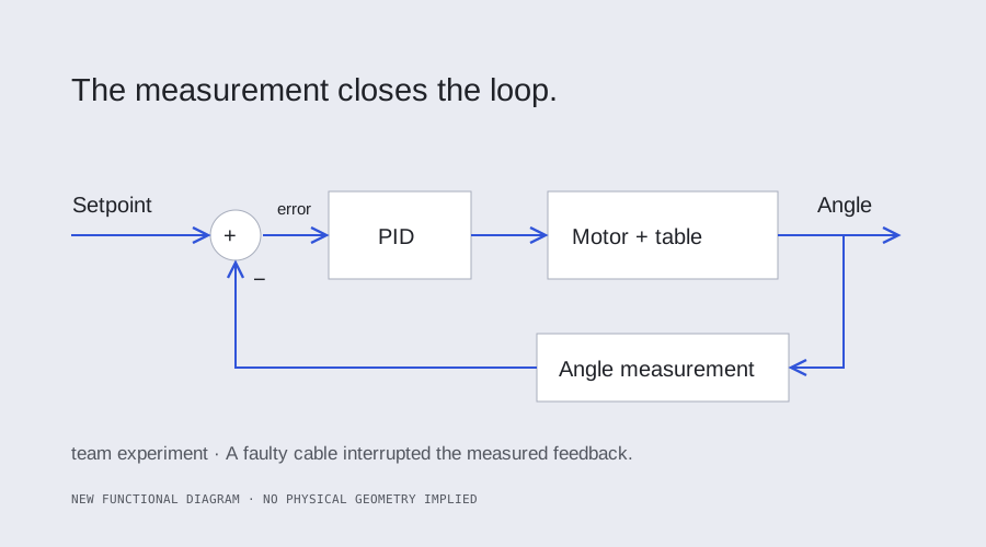
Our team modeled a motor-driven rotary table and developed a PID controller around its analog angle feedback. When the hardware behaved unexpectedly, we tracked the controller input and output while moving the table. The ADC reading stayed frozen. Replacing the AI1 feedback cable restored changing measurements and allowed us to evaluate the controller.
What the hardware demonstrated
After the cable replacement, we observed position control and used a hand-applied disturbance to check that the controller opposed the motion. That was a qualitative demonstration. The original response records also exposed a units problem: oscillations spaced about 0.16–0.17 seconds apart cannot support the report's frequency labels in hertz. The preserved records do not establish a precise measured bandwidth or a quantified recovery envelope.
A complete sampled reconstruction
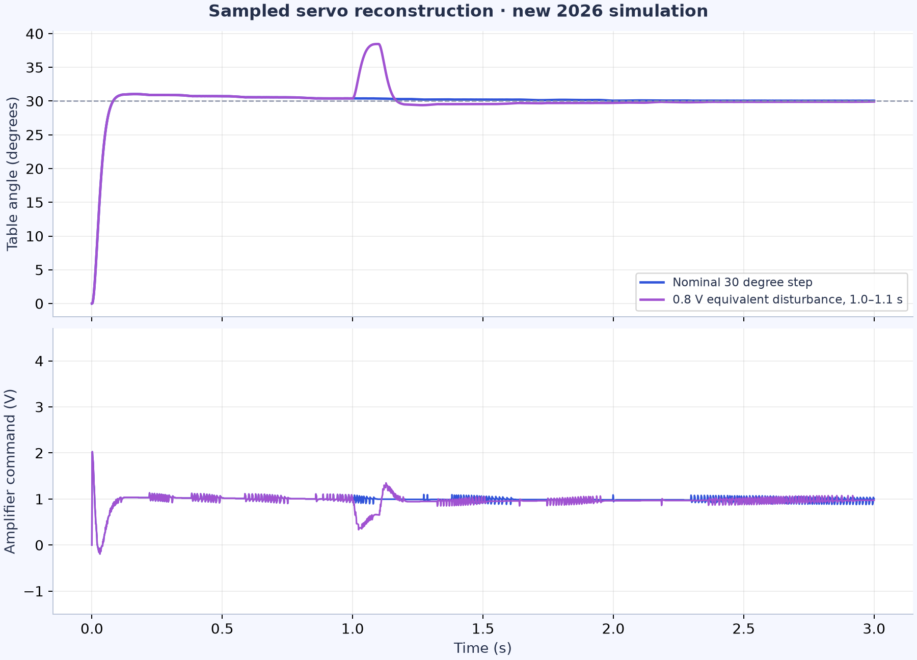
The 2026 reference defines the aggregate amplifier-to-angle plant, fits the recorded analog calibration and implements a 1 ms PID with feedforward, a filtered derivative, saturation antiwindup and quantized sensing and output. Six signed 15, 30 and 45 degree steps remain within one degree after at most 0.517 seconds over the three-second simulation, with 3.46% maximum tracking overshoot. These are new simulated results. Several degrees of residual error in the historical calibration prevent treating them as measured angle accuracy.
Make the fault behavior explicit
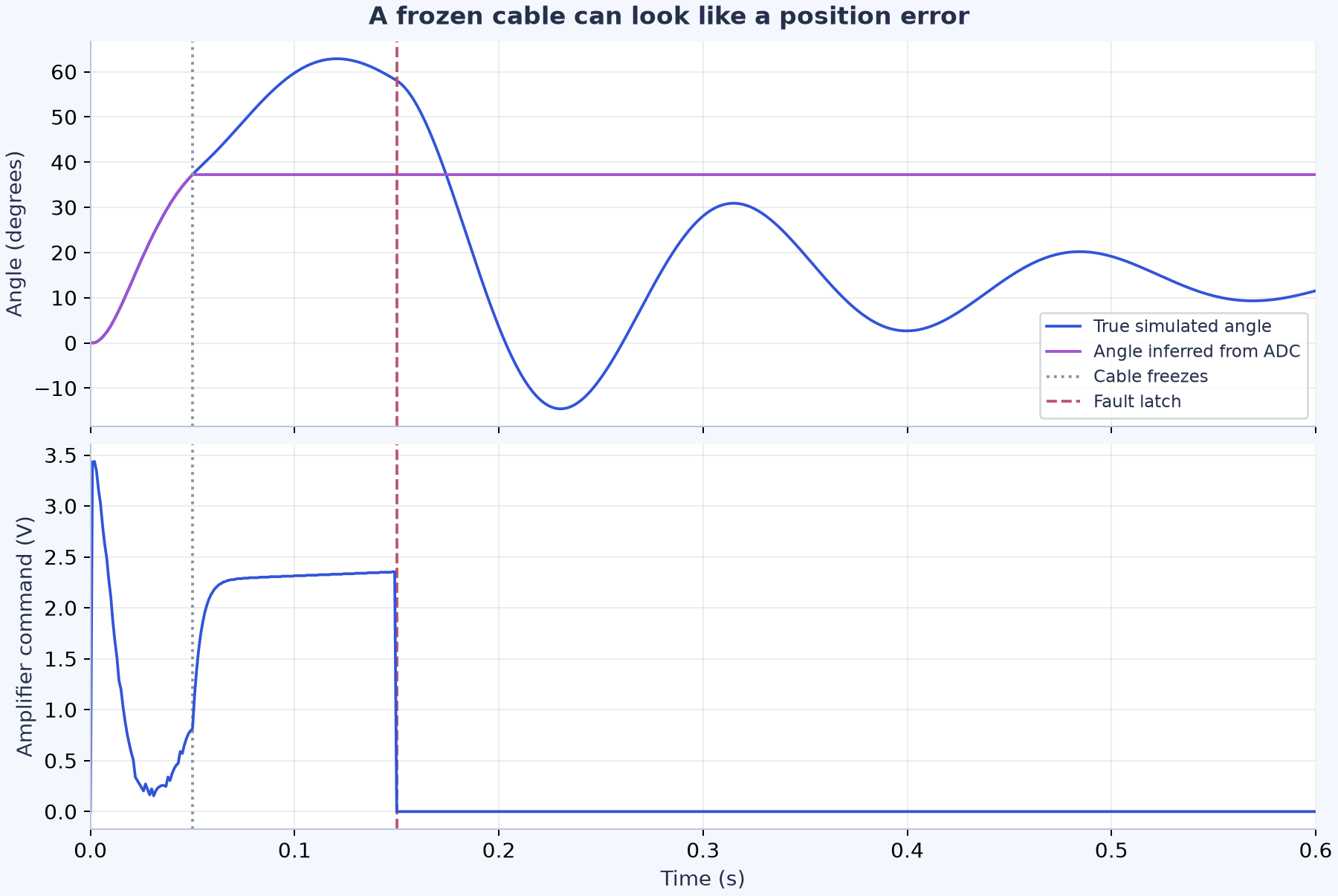
A frozen ADC code during a commanded move trips the new diagnostic in 100 ms and latches a zero-voltage command. Invalid ranges and timestamps are rejected at the control interface. A frozen signal near a stationary setpoint remains unobservable, and zero voltage does not establish a physical stop. Independent analytic plant calculations, timestep refinement, disturbance cases and parameter sensitivity checks bound what the digital result supports.
2026 sampled servo simulation
2026 sensing-fault simulation
Project context
Historical hardware work: Camden Boston, Mrunal Chavan and Christopher Hall, 2021. Separately authored digital reconstruction and simulations: 2026.
Historical photographs, footage, and plots retain their original dates. Later digital reconstructions are identified separately; their numerical checks do not establish hardware performance.